US8844090B2 - Tool for filling voids in turbine vanes and other articles - Google Patents
Tool for filling voids in turbine vanes and other articles Download PDFInfo
- Publication number
- US8844090B2 US8844090B2 US11/155,193 US15519305A US8844090B2 US 8844090 B2 US8844090 B2 US 8844090B2 US 15519305 A US15519305 A US 15519305A US 8844090 B2 US8844090 B2 US 8844090B2
- Authority
- US
- United States
- Prior art keywords
- tool
- pad
- pads
- airfoil
- voids
- Prior art date
- Legal status (The legal status is an assumption and is not a legal conclusion. Google has not performed a legal analysis and makes no representation as to the accuracy of the status listed.)
- Active, expires
Links
Images


Classifications
-
- F—MECHANICAL ENGINEERING; LIGHTING; HEATING; WEAPONS; BLASTING
- F01—MACHINES OR ENGINES IN GENERAL; ENGINE PLANTS IN GENERAL; STEAM ENGINES
- F01D—NON-POSITIVE DISPLACEMENT MACHINES OR ENGINES, e.g. STEAM TURBINES
- F01D5/00—Blades; Blade-carrying members; Heating, heat-insulating, cooling or antivibration means on the blades or the members
- F01D5/005—Repairing methods or devices
-
- B—PERFORMING OPERATIONS; TRANSPORTING
- B23—MACHINE TOOLS; METAL-WORKING NOT OTHERWISE PROVIDED FOR
- B23P—METAL-WORKING NOT OTHERWISE PROVIDED FOR; COMBINED OPERATIONS; UNIVERSAL MACHINE TOOLS
- B23P15/00—Making specific metal objects by operations not covered by a single other subclass or a group in this subclass
- B23P15/02—Making specific metal objects by operations not covered by a single other subclass or a group in this subclass turbine or like blades from one piece
-
- B—PERFORMING OPERATIONS; TRANSPORTING
- B23—MACHINE TOOLS; METAL-WORKING NOT OTHERWISE PROVIDED FOR
- B23P—METAL-WORKING NOT OTHERWISE PROVIDED FOR; COMBINED OPERATIONS; UNIVERSAL MACHINE TOOLS
- B23P15/00—Making specific metal objects by operations not covered by a single other subclass or a group in this subclass
- B23P15/04—Making specific metal objects by operations not covered by a single other subclass or a group in this subclass turbine or like blades from several pieces
-
- B—PERFORMING OPERATIONS; TRANSPORTING
- B23—MACHINE TOOLS; METAL-WORKING NOT OTHERWISE PROVIDED FOR
- B23P—METAL-WORKING NOT OTHERWISE PROVIDED FOR; COMBINED OPERATIONS; UNIVERSAL MACHINE TOOLS
- B23P6/00—Restoring or reconditioning objects
- B23P6/002—Repairing turbine components, e.g. moving or stationary blades, rotors
- B23P6/007—Repairing turbine components, e.g. moving or stationary blades, rotors using only additive methods, e.g. build-up welding
-
- B—PERFORMING OPERATIONS; TRANSPORTING
- B25—HAND TOOLS; PORTABLE POWER-DRIVEN TOOLS; MANIPULATORS
- B25B—TOOLS OR BENCH DEVICES NOT OTHERWISE PROVIDED FOR, FOR FASTENING, CONNECTING, DISENGAGING OR HOLDING
- B25B33/00—Hand tools not covered by any other group in this subclass
-
- B—PERFORMING OPERATIONS; TRANSPORTING
- B23—MACHINE TOOLS; METAL-WORKING NOT OTHERWISE PROVIDED FOR
- B23P—METAL-WORKING NOT OTHERWISE PROVIDED FOR; COMBINED OPERATIONS; UNIVERSAL MACHINE TOOLS
- B23P2700/00—Indexing scheme relating to the articles being treated, e.g. manufactured, repaired, assembled, connected or other operations covered in the subgroups
- B23P2700/06—Cooling passages of turbine components, e.g. unblocking or preventing blocking of cooling passages of turbine components
-
- F—MECHANICAL ENGINEERING; LIGHTING; HEATING; WEAPONS; BLASTING
- F05—INDEXING SCHEMES RELATING TO ENGINES OR PUMPS IN VARIOUS SUBCLASSES OF CLASSES F01-F04
- F05D—INDEXING SCHEME FOR ASPECTS RELATING TO NON-POSITIVE-DISPLACEMENT MACHINES OR ENGINES, GAS-TURBINES OR JET-PROPULSION PLANTS
- F05D2230/00—Manufacture
- F05D2230/20—Manufacture essentially without removing material
-
- F—MECHANICAL ENGINEERING; LIGHTING; HEATING; WEAPONS; BLASTING
- F05—INDEXING SCHEMES RELATING TO ENGINES OR PUMPS IN VARIOUS SUBCLASSES OF CLASSES F01-F04
- F05D—INDEXING SCHEME FOR ASPECTS RELATING TO NON-POSITIVE-DISPLACEMENT MACHINES OR ENGINES, GAS-TURBINES OR JET-PROPULSION PLANTS
- F05D2230/00—Manufacture
- F05D2230/30—Manufacture with deposition of material
-
- F—MECHANICAL ENGINEERING; LIGHTING; HEATING; WEAPONS; BLASTING
- F05—INDEXING SCHEMES RELATING TO ENGINES OR PUMPS IN VARIOUS SUBCLASSES OF CLASSES F01-F04
- F05D—INDEXING SCHEME FOR ASPECTS RELATING TO NON-POSITIVE-DISPLACEMENT MACHINES OR ENGINES, GAS-TURBINES OR JET-PROPULSION PLANTS
- F05D2230/00—Manufacture
- F05D2230/90—Coating; Surface treatment
-
- F—MECHANICAL ENGINEERING; LIGHTING; HEATING; WEAPONS; BLASTING
- F05—INDEXING SCHEMES RELATING TO ENGINES OR PUMPS IN VARIOUS SUBCLASSES OF CLASSES F01-F04
- F05D—INDEXING SCHEME FOR ASPECTS RELATING TO NON-POSITIVE-DISPLACEMENT MACHINES OR ENGINES, GAS-TURBINES OR JET-PROPULSION PLANTS
- F05D2260/00—Function
- F05D2260/20—Heat transfer, e.g. cooling
- F05D2260/202—Heat transfer, e.g. cooling by film cooling
Definitions
- This invention relates to a tool and an associated method for introducing an alloy paste concurrently into numerous voids in an article.
- Gas turbine engines include a turbine module for extracting energy from a stream of hot, gaseous combustion products that flow through a working medium flowpath.
- a typical turbine module includes at least one rotor disk with an array of circumferentially distributed blades secured to the disk. Each blade has an airfoil that spans radially across the flowpath.
- the turbine module also includes one or more arrays of circumferentially distributed vanes axially offset from the blades. Each vane also includes an airfoil that spans radially across the flowpath.
- the blades and vanes are exposed to the hot combustion gases, it is common practice to make them of temperature tolerant alloys such as nickel or cobalt base alloys. Despite the temperature tolerance of the alloys, it is also common practice to protect the blades and vanes from thermally induced damage.
- One means of protection is to apply a thermal barrier coating to those blade and vane surfaces, such as the airfoils, that are exposed to the hot gases.
- Another means is to cool the blades and vanes with a coolant, which is usually relatively cool, pressurized air extracted from an engine compressor. In a cooled blade or vane, the airfoil includes one or more internal cavities that receive the coolant.
- a multitude of coolant holes penetrates the walls of the airfoil to permit fluid communication from the internal cavity to the flowpath exposed surface.
- coolant flows into the cavity which then distributes the coolant to the holes.
- the coolant then flows through the holes to cool the airfoil.
- the coolant discharged from the holes spreads out to form a thin film of coolant on the airfoil surfaces, thus further protecting the airfoil.
- the coating is first applied to the substrate-alloy of the blade or vane, and then the coolant holes are installed so that they penetrate through both the coating and the airfoil wall.
- the holes may be installed by any suitable technique such as laser drilling, electron beam drilling or electro-discharge machining, although the holes are often referred to as “drilled” holes irrespective of the actual technique used to install them.
- flowpath side opening to refer to the hole opening at the flowpath side of the airfoil wall and “cavity side opening” to refer to the hole opening at the airfoil internal cavity.
- a typical repair involves stripping the thermal barrier coating, repairing any damage to the substrate alloy, and subsequently re-applying a replacement thermal barrier coating. This presents a difficulty because the coolant holes are already present in the airfoil walls. If the thermal coating were to be applied over these existing holes, it would then be necessary to install corresponding holes through the newly applied coating. These newly installed holes through the coating would have to be precisely aligned with the existing holes in the substrate alloy. However achieving such alignment is exceedingly difficult. Accordingly, standard practice is to completely plug the existing holes in the substrate with a suitable filler alloy prior to applying the replacement coating. This essentially restores the airfoil walls to their pre-drilled state. The replacement coating can then be applied, and new holes can be installed through both the replacement coating and the restored airfoil walls.
- the step of plugging the holes involves introducing a suitable alloy paste into the holes and then thermally processing the blade or vane so that the alloy paste solidifies in the holes.
- a suitable alloy paste has a metallurgical composition compatible with that of the parent alloy so that it forms a secure bond with the parent alloy and can withstand the rigors of service in an engine.
- it is necessary to completely plug the holes in the substrate. That is, the entire volume of each hole must be completely filled with the alloy paste in order to replicate the pre-drilled state of the airfoil walls.
- the repair paste does not readily flow into the holes and therefore must be forced into the holes.
- a paste injection system that includes a reservoir of paste, a hollow injection needle that receives the paste from the reservoir and dispenses it into the holes, and a source of pressurized air for forcing the paste through the needle.
- a technician inserts the dispensing end of the needle into the flowpath side opening of a hole and operates a foot pedal to apply the air pressure to the paste.
- the pressurization causes the paste to completely fill the hole until it oozes out the cavity side opening of the hole.
- the technician then repeats this process for each and every hole to be plugged.
- the paste is allowed to partially dry and stiffen, which leaves a small spur of semi-hardened paste projecting past the cavity side opening of each hole.
- the technician then uses a small spatula to reach into the cavity and chip off the spurs.
- the blade or vane is thermally processed to solidify the paste and bond the solidified alloy to the parent alloy.
- a tool for introducing a paste into voids in an article includes a pad having a surface shaped similarly to the shape of the region of the article that contains the voids.
- a specific example of the tool includes a first pad and a second pad, at least one of which has a surface shaped similarly to the shape of the region of the article containing the voids.
- the pads are joined to each other and are engageable with the article so that the similarly shaped surface hugs the void-containing region of the article to urge the paste into the voids.
- An associated method of filling multiple voids in an article includes applying a filler material to the article in the vicinity of the voids and urging the filler material concurrently into the multiple voids.
- FIG. 1 shows a turbine vane for a gas turbine engine including multiple rows of coolant holes and an alloy paste overlying some of the holes.
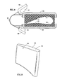
- FIG. 2 is a cross sectional view taken in the direction 2 - 2 of FIG. 1 showing the airfoil portion of the vane.
- FIG. 3 shows one variant of a tool for forcing the alloy paste concurrently into the numerous holes of FIG. 1 , the tool being illustrated in a relaxed state.
- FIG. 4 shows the vane of FIG. 1 with alloy paste applied to all the coolant holes and also shows the tool of FIG. 3 in a disengaged state so that the airfoil portion of the vane can be slipped into an opening in the tool.
- FIG. 5 shows the vane of FIG. 1 and the tool of FIG. 3 engaging the airfoil portion of the vane.
- FIG. 6 is a cross sectional view taken in the direction 6 - 6 of FIG. 5 .
- FIG. 7 shows a variant of the tool that includes a base and a handle.
- FIG. 8 shows another embodiment of the tool.
- FIG. 9 shows yet another embodiment of the tool.
- FIGS. 1 and 2 illustrate a vane 12 for the turbine module of a gas turbine engine.
- the vane includes radially inner and outer platforms 14 , 16 and an airfoil 18 .
- the platforms 14 , 16 cooperate with the platforms of circumferentially neighboring vanes to define the radially inner and outer boundaries of an annular working medium flowpath, and each airfoil spans radially across the flowpath.
- the airfoil has a concave pressure wall 20 , a convex suction wall 22 and a leading edge wall 24 , each with corresponding external surfaces 28 , 30 , 32 .
- the surfaces 28 , 30 , 32 collectively define the external surface of the airfoil.
- the pressure and suction walls extend chordwisely from an airfoil leading edge 34 to a trailing edge 36 .
- the pressure and suction surfaces 28 , 30 are spaced from each other by a chordwisely varying separation distance D 1 .
- the airfoil walls bound forward and aft internal cavities 40 , 42 for receiving coolant.
- Numerous coolant holes such as 44 , penetrate the pressure wall, the suction wall and the leading edge wall. These holes are present along the pressure surface, 28 the suction surface 30 and the leading edge surface 32 and represent voids that are required to be filled with an alloy paste.
- the holes extend from a first or flowpath side opening 46 at the flowpath or external side of the airfoil wall and second or cavity side opening 48 at one of the airfoil internal cavities 40 , 42 .
- Other voids such as small cracks, might also be present on the vane.
- Coolant windows 52 reside along the pressure side near the trailing edge to help exhaust coolant from the aft cavity 42 .
- the coolant windows 52 do not require plugging.
- the illustrated vane has three target regions populated by coolant holes that require plugging: target region A on the pressure surface, target region B on the suction surface and target region C on the leading edge surface.
- FIG. 3 illustrates a tool 54 that facilitates the introduction of an alloy paste concurrently into voids such as the numerous coolant holes 44 .
- the tool comprises a first pad 56 whose interior surface 58 is a working surface shaped substantially similarly to the surface shape of target region A. Since target region A is on the airfoil pressure surface, the pad 56 is referred to as a pressure surface pad.
- the tool also comprises a second pad 60 whose interior surface 62 is a working surface shaped substantially similarly to the surface shape of target region B. Since target region B is on the airfoil suction surface, the pad 60 is referred to as a suction surface pad.
- the pads are joined to each other by a joint, for example a hinge 66 .
- the hinge 66 is also a pad whose interior surface 68 is a working surface shaped similarly to the surface shape of target region C.
- the tool when the tool is not in use, it takes on a relaxed state in which the non-hinged end of the suction pad and the non-hinged end of the pressure pad lightly touch each other and the pads are spaced from each other by a chordwisely varying distance D 2 smaller than the separation distance D 1 between the airfoil suction and pressure surfaces.
- the pads are also displaceable relative to each other so that they can be positioned in both a disengaged position and an engaged position relative to the airfoil. In the disengaged position ( FIG. 4 ), the pads are spread apart so that the airfoil can be slipped into the opening between the pads. In the engaged position ( FIGS. 5 and 6 ) the pad interior surfaces 58 , 62 , 68 each hug the corresponding target regions A, B, C of the airfoil surface.
- the illustrated tool is monolithic in that it is a seamless, single piece unit molded of a single material.
- the pad material is flexible enough to substantially conform to the surface shape of the target regions, A, B, C, but stiff enough to urge an alloy paste into the holes as described below.
- One material known to be satisfactory is a room temperature vulcanizing (RTV) silicone rubber supplied by GE Silicones and referred to as RTV 668.
- RTV 668 room temperature vulcanizing
- the RTV 668 material has a Durometer hardness of between about 55 and 62 on the Shore A scale.
- a technician first positions an absorbent material, for example a foam rubber sponge 70 , into each of the cavities 40 , 42 (in FIG. 6 , the sponge is illustrated in only the forward cavity).
- the technician then applies a filler material to the airfoil surface in the vicinity of the coolant holes.
- the technician uses a syringe assembly 72 ( FIG. 1 ) to apply a bead of relatively high melting point alloy paste 74 over each of the several rows of coolant holes. This differs from the prior practice, in which the paste was forced, under pressure, into each and every hole, one hole at a time.
- the technician then uses the tool 54 to urge the paste concurrently into the holes 44 .
- the technician spreads apart the pads and slips the airfoil into the opening between the pads as seen in FIG. 4 .
- the technician then allows the pads to close onto the airfoil external surface as seen in FIGS. 5 and 6 . Because the pads do not close to their relaxed state of FIG. 3 , they exert a slight pressure on the beads of alloy paste to help force the paste into the holes.
- the technician manually applies additional pressure to the pressure surface pad and the suction surface pad.
- the pressure P exerted on the pads, and therefore on the target regions A, B, C, concurrently urges the alloy paste into the holes so that the paste fills the volume of each hole and excess paste 78 ( FIG.
- the sponge 70 at least partially absorbs the excess paste.
- An approximately chordwise component P c of the pressure P ensures that the working surface 68 of the hinge pad 66 hugs the leading edge surface 32 to reliably force the paste to completely fill the leading edge holes, even though these leading edge holes are significantly angularly offset from the direction of the pressure P.
- the technician then withdraws the sponges 70 from the cavities 40 , 42 and uses a cotton swab to wipe any residual paste off the cavity perimeter surface 80 .
- the use of the sponges and swab removes most of the excess paste. However a small amount of excess paste may still project beyond the cavity side openings 48 of one or more holes. This paste is allowed to partially dry and stiffen resulting in small spurs of semi-hardened paste that project into the cavity.
- the technician uses a spatula to chip off any of these spurs that are unacceptably large.
- the technician also disengages the tool 54 from the vane. The disengagement usually pulls a small amount of paste out of the flowpath side openings of the holes, leaving visually discernible shallow depressions.
- a second bead of alloy paste having a lower melting point than the paste in the holes is then applied over each row of holes.
- This second paste is not pressed into the holes, but nevertheless fills the shallow depressions.
- the vane is then thermally processed as already described to plug the holes.
- the processing also solidifies the second bead of paste.
- the hardened bead is machined off the airfoil to restore the airfoil external surface to its required aerodynamic shape.
- the illustrated vane has been described as including three target regions: A, B and C.
- This designation of target regions conforms to the conventional view in which the airfoil has an undifferentiated external surface which is thought of as comprising a pressure surface 28 , a suction surface 30 and a leading edge surface 32 .
- the target regions in the illustrated airfoil could have been described as a single continuous target region. In other articles, the target regions might be more distinct from each other.
- the corresponding tool surface would not necessarily need to mimic the shape of that region.
- the illustrated joint between pads 56 and 60 is a hinge that allows the pads to each rotate through an angle.
- the joint between the pads may take other forms, such as one that allows the pads to translate toward or away from each other with little or no relative angular displacement, or that permits both translation and angular displacement.
- FIG. 7 shows a variant of the tool that includes a base 84 and a handle 86 .
- the suction surface pad 60 is secured to the base 84 .
- the base is heavy enough to anchor the tool so that the technician need not hold onto the tool while spreading the pads apart.
- the base can be mounted to a workbench by fasteners or other means.
- the handle 86 extends from the pressure surface pad 56 .
- the handle permits a technician to more easily spread the pads away from each other and insert the vane.
- the pad 60 may be permanently mounted on the base or may be removably mounted so that the pad can be easily removed and cleaned.
- FIG. 8 shows a possible variant of the tool.
- the variant includes two rigid frame elements 88 connected to each other by a leaf spring 90 .
- Pads 92 , 94 with working surfaces 96 , 98 shaped similarly to the shape of a target region are mounted on the frame elements.
- the tool has been described as having multiple pads. However it may have only a single pad. For example, if it is necessary to introduce the alloy paste only into holes on the suction side of an airfoil, a simple single pad tool as seen in FIG. 9 could be effective. Moreover, the tool shown in FIGS. 3-6 could be viewed as a single pad tool if the target regions A, B and C are defined to be a single target region.
Abstract
Description
Claims (17)
Priority Applications (6)
| Application Number | Priority Date | Filing Date | Title |
|---|---|---|---|
| US11/155,193 US8844090B2 (en) | 2005-06-17 | 2005-06-17 | Tool for filling voids in turbine vanes and other articles |
| SG200604017A SG128602A1 (en) | 2005-06-17 | 2006-06-13 | Tool and method for filling voids in turbine vanesand other articles |
| DE602006009338T DE602006009338D1 (en) | 2005-06-17 | 2006-06-16 | Tool and method for filling openings in turbine blades and other articles |
| EP06253127A EP1734226B1 (en) | 2005-06-17 | 2006-06-16 | Tool and method for filling voids in turbine vanes and other articles |
| JP2006166772A JP4865412B2 (en) | 2005-06-17 | 2006-06-16 | Jig for filling pores of other articles such as turbine vanes and method therefor |
| KR1020060054244A KR20060132478A (en) | 2005-06-17 | 2006-06-16 | Tool and method for filling voids in turbine vanes and other articles |
Applications Claiming Priority (1)
| Application Number | Priority Date | Filing Date | Title |
|---|---|---|---|
| US11/155,193 US8844090B2 (en) | 2005-06-17 | 2005-06-17 | Tool for filling voids in turbine vanes and other articles |
Publications (2)
| Publication Number | Publication Date |
|---|---|
| US20070003690A1 US20070003690A1 (en) | 2007-01-04 |
| US8844090B2 true US8844090B2 (en) | 2014-09-30 |
Family
ID=36968610
Family Applications (1)
| Application Number | Title | Priority Date | Filing Date |
|---|---|---|---|
| US11/155,193 Active 2033-05-02 US8844090B2 (en) | 2005-06-17 | 2005-06-17 | Tool for filling voids in turbine vanes and other articles |
Country Status (6)
| Country | Link |
|---|---|
| US (1) | US8844090B2 (en) |
| EP (1) | EP1734226B1 (en) |
| JP (1) | JP4865412B2 (en) |
| KR (1) | KR20060132478A (en) |
| DE (1) | DE602006009338D1 (en) |
| SG (1) | SG128602A1 (en) |
Cited By (1)
| Publication number | Priority date | Publication date | Assignee | Title |
|---|---|---|---|---|
| US9061347B2 (en) * | 2012-01-18 | 2015-06-23 | Rolls-Royce Plc | Method of sealing cooling holes |
Families Citing this family (6)
| Publication number | Priority date | Publication date | Assignee | Title |
|---|---|---|---|---|
| US8146250B2 (en) * | 2008-05-30 | 2012-04-03 | General Electric Company | Method of replacing a composite airfoil |
| CN103292691A (en) * | 2012-02-29 | 2013-09-11 | 西门子公司 | Method for detecting cooling hole of combustion gas turbine blade |
| US9798839B2 (en) * | 2013-11-11 | 2017-10-24 | General Electric Company | System and methods of generating a computer model of a component |
| CN103978462B (en) * | 2014-05-19 | 2016-02-17 | 中国南方航空工业(集团)有限公司 | The whole instrument of blade type intonation |
| KR200480777Y1 (en) * | 2014-11-03 | 2016-07-05 | 한국남부발전 주식회사 | Gas Turbine Blade Washing Apparatus Using Fluid |
| US11313237B2 (en) | 2020-05-08 | 2022-04-26 | General Electric Company | Conforming coating mask for a component and system background |
Citations (43)
| Publication number | Priority date | Publication date | Assignee | Title |
|---|---|---|---|---|
| US3041685A (en) | 1961-07-14 | 1962-07-03 | Taccone Corp | Diaphragm molding machine |
| US3205527A (en) * | 1964-02-28 | 1965-09-14 | Owen A Laird | Drinking glass scrubbing and cleaning implement |
| US3226245A (en) | 1958-02-05 | 1965-12-28 | Polymer Corp | Coating method and apparatus |
| US3445880A (en) | 1967-05-09 | 1969-05-27 | Warner Arthur R | Blind cleaning appliance |
| US3487530A (en) | 1967-10-09 | 1970-01-06 | Abex Corp | Method of repairing casting defects |
| US3934300A (en) * | 1974-04-15 | 1976-01-27 | The Raymond Lee Organization, Inc. | Drinking glass cleaner |
| US3964666A (en) | 1975-03-31 | 1976-06-22 | Western Electric Company, Inc. | Bonding contact members to circuit boards |
| US3989087A (en) | 1973-06-28 | 1976-11-02 | British Cast Iron Research Assoc. | Making foundry moulds |
| US4042162A (en) | 1975-07-11 | 1977-08-16 | General Motors Corporation | Airfoil fabrication |
| US4050133A (en) | 1976-06-07 | 1977-09-27 | Cretella Salvatore | Method of refurbishing turbine vanes and the like |
| US4224494A (en) | 1976-10-05 | 1980-09-23 | Tocco-Stel | Brazing press for brazing claddings to pressings including a flat bottom surrounded by curved portions |
| JPS56140696A (en) | 1980-04-04 | 1981-11-04 | Sony Corp | Method of manufacturing circuit board |
| US4517702A (en) * | 1983-06-29 | 1985-05-21 | Jackson Frank W | Endoscopic scrub device |
| US4601081A (en) * | 1984-10-03 | 1986-07-22 | Sutton Raymond K | Disposable utensil for cleaning and disinfecting toilet seats and other articles |
| EP0269551A2 (en) | 1986-11-20 | 1988-06-01 | United Technologies Corporation | Methods for weld repairing hollow, air cooled turbine blades and vanes |
| US4866828A (en) | 1981-01-12 | 1989-09-19 | Refurbished Turbine Components Limited | Method of repairing turbine blades |
| US5116151A (en) * | 1991-07-12 | 1992-05-26 | Lytton Linda E | Ceiling fan cleaning apparatus |
| US5448828A (en) | 1993-04-02 | 1995-09-12 | Thyssen Industrie Ag | Process for preparing wear-resistant edges on turbine blades |
| US5565035A (en) | 1996-03-14 | 1996-10-15 | United Technologies Corporation | Fixture for masking a portion of an airfoil during application of a coating |
| US5701669A (en) | 1995-12-21 | 1997-12-30 | Mtu Motoren- Und Turbinen-Union Muenchen Gmbh | Repair method for lengthening turbine blades |
| EP0843026A1 (en) | 1996-10-16 | 1998-05-20 | Chromalloy Gas Turbine Corporation | Plating turbine engine components |
| US5873703A (en) | 1997-01-22 | 1999-02-23 | General Electric Company | Repair of gamma titanium aluminide articles |
| US5896616A (en) * | 1997-11-03 | 1999-04-27 | Egl 1, Inc. | Tire protectant applicator |
| EP0965390A1 (en) | 1998-06-17 | 1999-12-22 | United Technologies Corporation | Method and assembly for masking a flow directing assembly |
| EP1055480A2 (en) | 1999-05-28 | 2000-11-29 | General Electric Company | Repair of a recess in an article surface |
| EP1077126A1 (en) | 1999-08-16 | 2001-02-21 | General Electric Company | Injection formed hydrid airfoil |
| GB2354962A (en) | 1999-08-14 | 2001-04-11 | Colin Arthur Pugh | Airfoil holding device |
| US6258226B1 (en) | 1997-09-26 | 2001-07-10 | General Electric Company | Device for preventing plating of material in surface openings of turbine airfoils |
| US6273676B1 (en) | 1998-06-17 | 2001-08-14 | United Technologies Corporation | Method and assembly for masking a flow directing assembly |
| JP2002164649A (en) | 2000-11-28 | 2002-06-07 | Ngk Spark Plug Co Ltd | Method for manufacturing printed wiring board |
| US6454156B1 (en) | 2000-06-23 | 2002-09-24 | Siemens Westinghouse Power Corporation | Method for closing core printout holes in superalloy gas turbine blades |
| US6470568B2 (en) | 2000-02-23 | 2002-10-29 | Alstom (Switzerland) Ltd | Method for repairing a gas turbine component |
| EP1256635A1 (en) | 2001-05-08 | 2002-11-13 | General Electric Company | Method for applying diffusion aluminide coating on a selective area of a turbine engine component |
| US20030037436A1 (en) | 2001-08-23 | 2003-02-27 | Ducotey Howard S. | Method for repairing an apertured gas turbine component |
| DE10206447A1 (en) | 2002-02-11 | 2003-08-28 | Mtu Aero Engines Gmbh | Method and device for holding a metallic component to be connected and method for connecting a metallic component to another component |
| US6615470B2 (en) | 1997-12-15 | 2003-09-09 | General Electric Company | System and method for repairing cast articles |
| US6626350B2 (en) | 2000-06-23 | 2003-09-30 | Mtu Aero Engines Gmbh | Method of repairing metallic components |
| US20040226577A1 (en) * | 2003-03-11 | 2004-11-18 | Schaaf Philip J. | Cleaning apparatus and related methods |
| US6883988B1 (en) * | 2004-06-28 | 2005-04-26 | Beatrice Brown | Vertical blind cleaning tool |
| WO2005045199A1 (en) * | 2003-10-23 | 2005-05-19 | Rolls-Royce Plc | An apparatus and a method of applying a dry film lubricant to a rotor slot |
| US20050108840A1 (en) * | 2003-11-24 | 2005-05-26 | Marshall John C. | Fan blade cleaning tool and method |
| US20050172434A1 (en) * | 2004-02-05 | 2005-08-11 | Logan Audley Sr. | Toilet scrubber |
| US20060123577A1 (en) * | 2004-12-10 | 2006-06-15 | Luster Dean L | Apparatus for applying protective coatings to deck and stair balusters |
Family Cites Families (2)
| Publication number | Priority date | Publication date | Assignee | Title |
|---|---|---|---|---|
| FR2777917B1 (en) * | 1998-04-28 | 2001-05-25 | Bertrand Barre | CLOTHESPIN |
| US6109873A (en) * | 1998-06-17 | 2000-08-29 | United Technologies Corporation | Shield for masking a flow directing assembly |
-
2005
- 2005-06-17 US US11/155,193 patent/US8844090B2/en active Active
-
2006
- 2006-06-13 SG SG200604017A patent/SG128602A1/en unknown
- 2006-06-16 JP JP2006166772A patent/JP4865412B2/en not_active Expired - Fee Related
- 2006-06-16 EP EP06253127A patent/EP1734226B1/en active Active
- 2006-06-16 KR KR1020060054244A patent/KR20060132478A/en not_active Application Discontinuation
- 2006-06-16 DE DE602006009338T patent/DE602006009338D1/en active Active
Patent Citations (46)
| Publication number | Priority date | Publication date | Assignee | Title |
|---|---|---|---|---|
| US3226245A (en) | 1958-02-05 | 1965-12-28 | Polymer Corp | Coating method and apparatus |
| US3041685A (en) | 1961-07-14 | 1962-07-03 | Taccone Corp | Diaphragm molding machine |
| US3205527A (en) * | 1964-02-28 | 1965-09-14 | Owen A Laird | Drinking glass scrubbing and cleaning implement |
| US3445880A (en) | 1967-05-09 | 1969-05-27 | Warner Arthur R | Blind cleaning appliance |
| US3487530A (en) | 1967-10-09 | 1970-01-06 | Abex Corp | Method of repairing casting defects |
| US3989087A (en) | 1973-06-28 | 1976-11-02 | British Cast Iron Research Assoc. | Making foundry moulds |
| US3934300A (en) * | 1974-04-15 | 1976-01-27 | The Raymond Lee Organization, Inc. | Drinking glass cleaner |
| US3964666A (en) | 1975-03-31 | 1976-06-22 | Western Electric Company, Inc. | Bonding contact members to circuit boards |
| US4042162A (en) | 1975-07-11 | 1977-08-16 | General Motors Corporation | Airfoil fabrication |
| US4050133A (en) | 1976-06-07 | 1977-09-27 | Cretella Salvatore | Method of refurbishing turbine vanes and the like |
| US4224494A (en) | 1976-10-05 | 1980-09-23 | Tocco-Stel | Brazing press for brazing claddings to pressings including a flat bottom surrounded by curved portions |
| JPS56140696A (en) | 1980-04-04 | 1981-11-04 | Sony Corp | Method of manufacturing circuit board |
| US4866828A (en) | 1981-01-12 | 1989-09-19 | Refurbished Turbine Components Limited | Method of repairing turbine blades |
| US4517702A (en) * | 1983-06-29 | 1985-05-21 | Jackson Frank W | Endoscopic scrub device |
| US4601081A (en) * | 1984-10-03 | 1986-07-22 | Sutton Raymond K | Disposable utensil for cleaning and disinfecting toilet seats and other articles |
| EP0269551A2 (en) | 1986-11-20 | 1988-06-01 | United Technologies Corporation | Methods for weld repairing hollow, air cooled turbine blades and vanes |
| US5116151A (en) * | 1991-07-12 | 1992-05-26 | Lytton Linda E | Ceiling fan cleaning apparatus |
| US5448828A (en) | 1993-04-02 | 1995-09-12 | Thyssen Industrie Ag | Process for preparing wear-resistant edges on turbine blades |
| US5701669A (en) | 1995-12-21 | 1997-12-30 | Mtu Motoren- Und Turbinen-Union Muenchen Gmbh | Repair method for lengthening turbine blades |
| US5565035A (en) | 1996-03-14 | 1996-10-15 | United Technologies Corporation | Fixture for masking a portion of an airfoil during application of a coating |
| EP0843026A1 (en) | 1996-10-16 | 1998-05-20 | Chromalloy Gas Turbine Corporation | Plating turbine engine components |
| US5873703A (en) | 1997-01-22 | 1999-02-23 | General Electric Company | Repair of gamma titanium aluminide articles |
| US6258226B1 (en) | 1997-09-26 | 2001-07-10 | General Electric Company | Device for preventing plating of material in surface openings of turbine airfoils |
| US5896616A (en) * | 1997-11-03 | 1999-04-27 | Egl 1, Inc. | Tire protectant applicator |
| US6615470B2 (en) | 1997-12-15 | 2003-09-09 | General Electric Company | System and method for repairing cast articles |
| EP0965390A1 (en) | 1998-06-17 | 1999-12-22 | United Technologies Corporation | Method and assembly for masking a flow directing assembly |
| US6273676B1 (en) | 1998-06-17 | 2001-08-14 | United Technologies Corporation | Method and assembly for masking a flow directing assembly |
| JP2001115857A (en) | 1999-05-28 | 2001-04-24 | General Electric Co <Ge> | Repair of recess in article surface |
| US6283356B1 (en) | 1999-05-28 | 2001-09-04 | General Electric Company | Repair of a recess in an article surface |
| EP1055480A2 (en) | 1999-05-28 | 2000-11-29 | General Electric Company | Repair of a recess in an article surface |
| GB2354962A (en) | 1999-08-14 | 2001-04-11 | Colin Arthur Pugh | Airfoil holding device |
| EP1077126A1 (en) | 1999-08-16 | 2001-02-21 | General Electric Company | Injection formed hydrid airfoil |
| US6470568B2 (en) | 2000-02-23 | 2002-10-29 | Alstom (Switzerland) Ltd | Method for repairing a gas turbine component |
| US6454156B1 (en) | 2000-06-23 | 2002-09-24 | Siemens Westinghouse Power Corporation | Method for closing core printout holes in superalloy gas turbine blades |
| US6626350B2 (en) | 2000-06-23 | 2003-09-30 | Mtu Aero Engines Gmbh | Method of repairing metallic components |
| JP2002164649A (en) | 2000-11-28 | 2002-06-07 | Ngk Spark Plug Co Ltd | Method for manufacturing printed wiring board |
| EP1256635A1 (en) | 2001-05-08 | 2002-11-13 | General Electric Company | Method for applying diffusion aluminide coating on a selective area of a turbine engine component |
| US20030037436A1 (en) | 2001-08-23 | 2003-02-27 | Ducotey Howard S. | Method for repairing an apertured gas turbine component |
| DE10206447A1 (en) | 2002-02-11 | 2003-08-28 | Mtu Aero Engines Gmbh | Method and device for holding a metallic component to be connected and method for connecting a metallic component to another component |
| US20040226577A1 (en) * | 2003-03-11 | 2004-11-18 | Schaaf Philip J. | Cleaning apparatus and related methods |
| WO2005045199A1 (en) * | 2003-10-23 | 2005-05-19 | Rolls-Royce Plc | An apparatus and a method of applying a dry film lubricant to a rotor slot |
| US7917988B2 (en) * | 2003-10-23 | 2011-04-05 | Rolls-Royce Plc | Apparatus and a method of applying a dry film lubricant to a rotor slot |
| US20050108840A1 (en) * | 2003-11-24 | 2005-05-26 | Marshall John C. | Fan blade cleaning tool and method |
| US20050172434A1 (en) * | 2004-02-05 | 2005-08-11 | Logan Audley Sr. | Toilet scrubber |
| US6883988B1 (en) * | 2004-06-28 | 2005-04-26 | Beatrice Brown | Vertical blind cleaning tool |
| US20060123577A1 (en) * | 2004-12-10 | 2006-06-15 | Luster Dean L | Apparatus for applying protective coatings to deck and stair balusters |
Cited By (1)
| Publication number | Priority date | Publication date | Assignee | Title |
|---|---|---|---|---|
| US9061347B2 (en) * | 2012-01-18 | 2015-06-23 | Rolls-Royce Plc | Method of sealing cooling holes |
Also Published As
| Publication number | Publication date |
|---|---|
| DE602006009338D1 (en) | 2009-11-05 |
| KR20060132478A (en) | 2006-12-21 |
| EP1734226B1 (en) | 2009-09-23 |
| EP1734226A1 (en) | 2006-12-20 |
| US20070003690A1 (en) | 2007-01-04 |
| SG128602A1 (en) | 2007-01-30 |
| JP4865412B2 (en) | 2012-02-01 |
| JP2006348943A (en) | 2006-12-28 |
Similar Documents
| Publication | Publication Date | Title |
|---|---|---|
| US8844090B2 (en) | Tool for filling voids in turbine vanes and other articles | |
| CA2481111C (en) | Process of masking cooling holes of a gas turbine component | |
| EP1507881B1 (en) | Process of masking cooling holes of a gas turbine component | |
| EP1212167B1 (en) | Method for replacing a turbine vane airfoil | |
| US9186757B2 (en) | Method of providing a turbine blade tip repair | |
| EP2108504B1 (en) | Method for repair of a gas turbine engine part metallic doubler and repaired part | |
| CZ20002804A3 (en) | Method of repairing cast products of high alloys by making use of metallurgically bonded conical filler plug | |
| EP2372101B1 (en) | Method of forming a seal element | |
| EP2855033B1 (en) | Coating for cooling air holes | |
| US9844897B2 (en) | Method and apparatus for supporting blades | |
| EP2239083A1 (en) | Internally supported airfoil and method for internally supporting a hollow airfoil during manufacturing. | |
| EP2163729A2 (en) | Turbine bucket with dovetail seal and related method | |
| EP2865847A1 (en) | Method and apparatus for supporting blades | |
| JP2002276389A (en) | Fixture and supplying method of filling material | |
| US7387817B2 (en) | Method for masking a workpiece before encapsulation in a casting block | |
| US20130266437A1 (en) | Compressor guide-vane stage for a turbine engine | |
| US20160032736A1 (en) | Coating process and coated article | |
| EP2617940A2 (en) | Method of sealing cooling holes of an airfoil component of a turbine blade | |
| EP2517860B1 (en) | De-mold liner based injection tool and injection molding method | |
| EP2618031B1 (en) | Method of sealing a nozzle guide vane to a housing | |
| EP3409456B1 (en) | Aircraft repair patch application tool | |
| JPH11179604A (en) | Mounting method and mounting device for external blade type cutter |
Legal Events
| Date | Code | Title | Description |
|---|---|---|---|
| AS | Assignment |
Owner name: UNITED TECHNOLOGIES CORPORATION, CONNECTICUT Free format text: ASSIGNMENT OF ASSIGNORS INTEREST;ASSIGNORS:D'AMOUR, BRIAN E.;THURSTON, RAYMOND D.;REEL/FRAME:016708/0375 Effective date: 20050616 |
|
| STCF | Information on status: patent grant |
Free format text: PATENTED CASE |
|
| MAFP | Maintenance fee payment |
Free format text: PAYMENT OF MAINTENANCE FEE, 4TH YEAR, LARGE ENTITY (ORIGINAL EVENT CODE: M1551) Year of fee payment: 4 |
|
| AS | Assignment |
Owner name: RAYTHEON TECHNOLOGIES CORPORATION, MASSACHUSETTS Free format text: CHANGE OF NAME;ASSIGNOR:UNITED TECHNOLOGIES CORPORATION;REEL/FRAME:054062/0001 Effective date: 20200403 |
|
| AS | Assignment |
Owner name: RAYTHEON TECHNOLOGIES CORPORATION, CONNECTICUT Free format text: CORRECTIVE ASSIGNMENT TO CORRECT THE AND REMOVE PATENT APPLICATION NUMBER 11886281 AND ADD PATENT APPLICATION NUMBER 14846874. TO CORRECT THE RECEIVING PARTY ADDRESS PREVIOUSLY RECORDED AT REEL: 054062 FRAME: 0001. ASSIGNOR(S) HEREBY CONFIRMS THE CHANGE OF ADDRESS;ASSIGNOR:UNITED TECHNOLOGIES CORPORATION;REEL/FRAME:055659/0001 Effective date: 20200403 |
|
| MAFP | Maintenance fee payment |
Free format text: PAYMENT OF MAINTENANCE FEE, 8TH YEAR, LARGE ENTITY (ORIGINAL EVENT CODE: M1552); ENTITY STATUS OF PATENT OWNER: LARGE ENTITY Year of fee payment: 8 |
|
| AS | Assignment |
Owner name: RTX CORPORATION, CONNECTICUT Free format text: CHANGE OF NAME;ASSIGNOR:RAYTHEON TECHNOLOGIES CORPORATION;REEL/FRAME:064714/0001 Effective date: 20230714 |