US2485700A - Tool for forcing resilient tire beads into the drop center of a wheel rim - Google Patents
Tool for forcing resilient tire beads into the drop center of a wheel rim Download PDFInfo
- Publication number
- US2485700A US2485700A US581442A US58144245A US2485700A US 2485700 A US2485700 A US 2485700A US 581442 A US581442 A US 581442A US 58144245 A US58144245 A US 58144245A US 2485700 A US2485700 A US 2485700A
- Authority
- US
- United States
- Prior art keywords
- tool
- tire
- yoke
- wheel rim
- rim
- Prior art date
- Legal status (The legal status is an assumption and is not a legal conclusion. Google has not performed a legal analysis and makes no representation as to the accuracy of the status listed.)
- Expired - Lifetime
Links
Images
Classifications
-
- B—PERFORMING OPERATIONS; TRANSPORTING
- B60—VEHICLES IN GENERAL
- B60C—VEHICLE TYRES; TYRE INFLATION; TYRE CHANGING; CONNECTING VALVES TO INFLATABLE ELASTIC BODIES IN GENERAL; DEVICES OR ARRANGEMENTS RELATED TO TYRES
- B60C25/00—Apparatus or tools adapted for mounting, removing or inspecting tyres
- B60C25/01—Apparatus or tools adapted for mounting, removing or inspecting tyres for removing tyres from or mounting tyres on wheels
- B60C25/02—Tyre levers or the like, e.g. hand-held
Definitions
- This invention relates to a tool for use in removing tires from wheel rims.
- An object of the invention is to provide a simple and easily carried tool which constitutes an efiective means for performing the desired result.
- Another object is to provide a tool designed to push the bead of a tire into the drop center of a wheel rim, after the bead has been pried loose by means of another tire tool, and to provide slippage when the tire is lifted from the rim by means of a tire iron or the like.
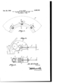
- Figure l is a side elevation showing a group of these tools applied to a wheel rim and tire, said rim and tire being shown by broken lines.
- Figure 2 is an enlarged section on line 22 Figure 1.
- Figure 3 is a bottom plan view of the tool shown in Figure 2.
- i designates the body of the tool which is in the form of a yoke and is curved along its outer periphery from one end to the other.
- the recess 2 provided by the yoke is proportioned to receive freely one side of a wheel rim R and there is formed in the periphery of this yoke adjacent to one of its ends, a socket 3 in which is journaled a roller 4 which projects a short distance outwardly beyond the yoke.
- a screw 5 which extends into recess 2 and is provided, within the recess, with a foot 6 having a ball and socket connection with the screw, as indicated at I.
- a handle 8 or the like is provided at the outer end of the screw whereby it can be turned readily.
- One or more of these tools can be used during a single operation. As a general rule, three are found desirable.
- a portion of the tire bead is separated from the rim flange with a suitable tire iron sufiiciently to permit insertion by hand of the, end 9 of one of the devices.
- other similar devices are applied successively to adjacent portions of the tire bead and rim flange until they are properly separated to permit complete removal of the tire with a tire iron. Stated otherwise, the devices are placed in position successively astride one flange of the rim R at short distances apart with the end 9 of each yoke extended downwardly into the rim and the screw 5 inclined downwardly as far as possible.
- the outer periphery of the yoke is curved from one end to the other, and is outwardly bulged as to that portion of the yoke adjacent the roller (see Figure 2).
- this outer surface acts as a cam, thereby supplementing the action of the roller in shifting the tire relative to the rim on which the tool is mounted.
- the parts can adapt themselves readily to difierent angles relative to the rim following the shifting of the tire.
- a tire tool comprising a yoke having its outer side curvingly bulged to define a cam surface adjacent one end, said end being proportioned for insertion between a wheel rim flange and a loosened tire to be removed, the yoke having a recess formed in its inner side proportioned to receive the rim flange loosely, an antifriction roller journaled within the yoke and projecting outwardly therefrom, said roller being disposed close to the cam surface and between the cam surface and the inserted end of the yoke, the roller being mounted to move radially of a tire engageable thereby as said yoke is swung about said rim flange, thus to bring the roller and cam face sucfeessively against the tire side wall to press it inwardly away from the rim flange, and a screw adjustably mounted in the other end of the yoke and having its inner end projecting into the recess whereby to tighten the yoke to the
Description
Oct. 25, 1949. M M COOK 2,485,700
TOOL FOR FORCING REILIENT TIRE BEADS INTO THE DROP CENTER OF WHEEL RIMS Filed March 7, 1945 INVENTOR.
flTTOF/VEY Patented Oct. 25, 1949 TOOL FOR FORCING RESILIENT TIRE.
BEADS WHEEL RIM INTO THE DROP CENTER OF A Milford Marcuise Cook, Visalia, Calif. Application March 7, 1945, Serial No. 581,442
1 Claim. 1
This invention relates to a tool for use in removing tires from wheel rims.
An object of the invention is to provide a simple and easily carried tool which constitutes an efiective means for performing the desired result.
Another object is to provide a tool designed to push the bead of a tire into the drop center of a wheel rim, after the bead has been pried loose by means of another tire tool, and to provide slippage when the tire is lifted from the rim by means of a tire iron or the like.
With the foregoing and other objects in view which will appear as the description proceeds, the invention consists of certain novel details of construction and combinations of parts hereinafter more fully described and pointed out in the claim, it being understood that changes may be made in the construction and arrangement of parts without departing from the spirit of the invention as claimed.
In the accompanying drawing the preferred form of the invention has been shown.
In said drawing:
Figure l is a side elevation showing a group of these tools applied to a wheel rim and tire, said rim and tire being shown by broken lines.
Figure 2 is an enlarged section on line 22 Figure 1.
Figure 3 is a bottom plan view of the tool shown in Figure 2.
Referring to the figures by characters of reference, i designates the body of the tool which is in the form of a yoke and is curved along its outer periphery from one end to the other. The recess 2 provided by the yoke is proportioned to receive freely one side of a wheel rim R and there is formed in the periphery of this yoke adjacent to one of its ends, a socket 3 in which is journaled a roller 4 which projects a short distance outwardly beyond the yoke.
In the opposite portion of the yoke there is mounted a screw 5 which extends into recess 2 and is provided, within the recess, with a foot 6 having a ball and socket connection with the screw, as indicated at I. A handle 8 or the like is provided at the outer end of the screw whereby it can be turned readily.
One or more of these tools can be used during a single operation. As a general rule, three are found desirable. In use, a portion of the tire bead is separated from the rim flange with a suitable tire iron sufiiciently to permit insertion by hand of the, end 9 of one of the devices. Then, other similar devices are applied successively to adjacent portions of the tire bead and rim flange until they are properly separated to permit complete removal of the tire with a tire iron. Stated otherwise, the devices are placed in position successively astride one flange of the rim R at short distances apart with the end 9 of each yoke extended downwardly into the rim and the screw 5 inclined downwardly as far as possible. This brings the roller well above and outwardly from the position shown in Figure 2 so that the end S can be pressed downwardly by hand or otherwise into position between the sides of the tire and rim. Using the screw 5 as a handle or lever, the device is pulled upwardly with the end 9 as a fulcrum and wheel 4 thus is brought into position where it can roll radially of the engaged portion of the tire and at the same time push the tire inwardly substantially to the position shown in Figure 2. Screw 5 is then turned inwardly so as to force the foot 6 against the side of the rim. This will lock the device with the tire pressed inwardly by the roller and held partly unseated as shown at T in Figure 2. After the tire has thus been pressed in at spaced points, it can be removed by suitable leverage exerted against the opposite side, the rollers of the several tools proe viding a slippage which will facilitate the removal.
Importance is attached to the fact that the tool used as explained is light and compact and can be easily carried. Furthermore, it is handled readily and avoids the necessity of employing large complicated devices such as commonly used.
It will be noted that the outer periphery of the yoke is curved from one end to the other, and is outwardly bulged as to that portion of the yoke adjacent the roller (see Figure 2). Thus when the yoke is swung from one position to another this outer surface acts as a cam, thereby supplementing the action of the roller in shifting the tire relative to the rim on which the tool is mounted.
By mounting the foot 6 so that it can move on the screw 5, the parts can adapt themselves readily to difierent angles relative to the rim following the shifting of the tire.
What is claimed is:
A tire tool comprising a yoke having its outer side curvingly bulged to define a cam surface adjacent one end, said end being proportioned for insertion between a wheel rim flange and a loosened tire to be removed, the yoke having a recess formed in its inner side proportioned to receive the rim flange loosely, an antifriction roller journaled within the yoke and projecting outwardly therefrom, said roller being disposed close to the cam surface and between the cam surface and the inserted end of the yoke, the roller being mounted to move radially of a tire engageable thereby as said yoke is swung about said rim flange, thus to bring the roller and cam face sucfeessively against the tire side wall to press it inwardly away from the rim flange, and a screw adjustably mounted in the other end of the yoke and having its inner end projecting into the recess whereby to tighten the yoke to the rim flange, the outer end of the screw being extended outwardly from the yoke to provide a lever.
MILFORD MARCUISE COOK.
REFERENCES CITED The following references are of record in the file of this patent:
Number Number 4 UNITED STATES PATENTS Name Date Hussey Nov. 6, 1906 Dahl Nov. 5, 1912 Edington et a1 Mar. 17, 1914 Reininger Oct. 21, 1919 Smith et al June 24, 1924 Mjelva May 26, 1931 Mueller Mar. 27, 1934 FOREIGN PATENTS Country Date Great Britain July 4, 1935
Priority Applications (1)
| Application Number | Priority Date | Filing Date | Title |
|---|---|---|---|
| US581442A US2485700A (en) | 1945-03-07 | 1945-03-07 | Tool for forcing resilient tire beads into the drop center of a wheel rim |
Applications Claiming Priority (1)
| Application Number | Priority Date | Filing Date | Title |
|---|---|---|---|
| US581442A US2485700A (en) | 1945-03-07 | 1945-03-07 | Tool for forcing resilient tire beads into the drop center of a wheel rim |
Publications (1)
| Publication Number | Publication Date |
|---|---|
| US2485700A true US2485700A (en) | 1949-10-25 |
Family
ID=24325211
Family Applications (1)
| Application Number | Title | Priority Date | Filing Date |
|---|---|---|---|
| US581442A Expired - Lifetime US2485700A (en) | 1945-03-07 | 1945-03-07 | Tool for forcing resilient tire beads into the drop center of a wheel rim |
Country Status (1)
| Country | Link |
|---|---|
| US (1) | US2485700A (en) |
Cited By (4)
| Publication number | Priority date | Publication date | Assignee | Title |
|---|---|---|---|---|
| FR2765833A1 (en) * | 1997-07-09 | 1999-01-15 | Hofmann Werkstatt Technik | HEEL CLAMP FOR MOUNTING A TIRE |
| US20090178768A1 (en) * | 2008-01-10 | 2009-07-16 | Societa' Italiana Costruzioni Elettromeccaniche - S.I.C.E. - S.P.A. | Device to ease the mounting or demounting of tyres |
| US20150239310A1 (en) * | 2014-02-27 | 2015-08-27 | Timothy Voegeli | Tubeless tire rim clamp assembly |
| US10766318B2 (en) | 2018-07-06 | 2020-09-08 | Snap-On Incorporated | Tire lever |
Citations (8)
| Publication number | Priority date | Publication date | Assignee | Title |
|---|---|---|---|---|
| US834908A (en) * | 1905-11-04 | 1906-11-06 | Patrick L Hussey | Tool for detaching and resetting tires. |
| US1043208A (en) * | 1911-10-05 | 1912-11-05 | Benjamin Dahl | Means for mounting punctureless tires on wheel-rims. |
| US1090290A (en) * | 1912-04-18 | 1914-03-17 | William F Edgington | Tire-tool. |
| US1319617A (en) * | 1919-10-21 | Inger | ||
| US1498816A (en) * | 1920-10-29 | 1924-06-24 | John A Smith | Tire remover |
| US1806947A (en) * | 1931-05-26 | Tire behoving tool | ||
| US1952453A (en) * | 1932-02-13 | 1934-03-27 | George C Mueller | Portable clamp |
| GB431287A (en) * | 1934-04-13 | 1935-07-04 | William Hardwick | An improved tyre lever |
-
1945
- 1945-03-07 US US581442A patent/US2485700A/en not_active Expired - Lifetime
Patent Citations (8)
| Publication number | Priority date | Publication date | Assignee | Title |
|---|---|---|---|---|
| US1319617A (en) * | 1919-10-21 | Inger | ||
| US1806947A (en) * | 1931-05-26 | Tire behoving tool | ||
| US834908A (en) * | 1905-11-04 | 1906-11-06 | Patrick L Hussey | Tool for detaching and resetting tires. |
| US1043208A (en) * | 1911-10-05 | 1912-11-05 | Benjamin Dahl | Means for mounting punctureless tires on wheel-rims. |
| US1090290A (en) * | 1912-04-18 | 1914-03-17 | William F Edgington | Tire-tool. |
| US1498816A (en) * | 1920-10-29 | 1924-06-24 | John A Smith | Tire remover |
| US1952453A (en) * | 1932-02-13 | 1934-03-27 | George C Mueller | Portable clamp |
| GB431287A (en) * | 1934-04-13 | 1935-07-04 | William Hardwick | An improved tyre lever |
Cited By (6)
| Publication number | Priority date | Publication date | Assignee | Title |
|---|---|---|---|---|
| FR2765833A1 (en) * | 1997-07-09 | 1999-01-15 | Hofmann Werkstatt Technik | HEEL CLAMP FOR MOUNTING A TIRE |
| US6179032B1 (en) | 1997-07-09 | 2001-01-30 | Hofmann Werkstatt-Technik Gmbh | Bead depressor |
| US20090178768A1 (en) * | 2008-01-10 | 2009-07-16 | Societa' Italiana Costruzioni Elettromeccaniche - S.I.C.E. - S.P.A. | Device to ease the mounting or demounting of tyres |
| US20150239310A1 (en) * | 2014-02-27 | 2015-08-27 | Timothy Voegeli | Tubeless tire rim clamp assembly |
| US9873297B2 (en) * | 2014-02-27 | 2018-01-23 | Timothy Voegeli | Tubeless tire rim clamp assembly |
| US10766318B2 (en) | 2018-07-06 | 2020-09-08 | Snap-On Incorporated | Tire lever |
Similar Documents
| Publication | Publication Date | Title |
|---|---|---|
| US4642866A (en) | Hub removing device and method | |
| US3389453A (en) | Tire installation tool | |
| US2606602A (en) | Pneumatic tire bead loosening tool | |
| US1567025A (en) | Automobile tire tool | |
| US2485700A (en) | Tool for forcing resilient tire beads into the drop center of a wheel rim | |
| US1806947A (en) | Tire behoving tool | |
| US3928902A (en) | Tool for tubeless tire valves | |
| US2274126A (en) | Weight removing pliers | |
| US2433113A (en) | Lever actuated tire bead forcing device | |
| US3302275A (en) | Tire tool | |
| US1495884A (en) | Tire tool | |
| US2619158A (en) | Lever actuated tire bead forcing tool | |
| US1480371A (en) | Appliance for setting and removing tires | |
| US2672184A (en) | Lever actuated tire bead forcing device | |
| US1776804A (en) | Tire tool | |
| US2317072A (en) | Tire tool | |
| US1569310A (en) | Tire lever | |
| US2615507A (en) | Circumferentially traveling type tire removing tool | |
| GB581553A (en) | Improvements in or relating to tire removing tools | |
| US2344970A (en) | Antiskid device for the tires of motor vehicle wheels | |
| US1619426A (en) | Tire tool | |
| US2548033A (en) | Axially shifting type jack operated tire removing device | |
| GB143403A (en) | Improved devices for placing pneumatic tyres on wheel rims and for removing them | |
| GB503274A (en) | Means for removing and replacing pneumatic tyres of vehicle wheels | |
| US2290887A (en) | Tire changing tool |