US1854740A - Holder - Google Patents
Holder Download PDFInfo
- Publication number
- US1854740A US1854740A US521746A US52174631A US1854740A US 1854740 A US1854740 A US 1854740A US 521746 A US521746 A US 521746A US 52174631 A US52174631 A US 52174631A US 1854740 A US1854740 A US 1854740A
- Authority
- US
- United States
- Prior art keywords
- wire
- base
- holder
- channel
- standard
- Prior art date
- Legal status (The legal status is an assumption and is not a legal conclusion. Google has not performed a legal analysis and makes no representation as to the accuracy of the status listed.)
- Expired - Lifetime
Links
- 238000010276 construction Methods 0.000 description 4
- 239000000463 material Substances 0.000 description 4
- 239000002184 metal Substances 0.000 description 3
- 229920002160 Celluloid Polymers 0.000 description 2
- 238000000576 coating method Methods 0.000 description 2
- 241001635598 Enicostema Species 0.000 description 1
- 206010027626 Milia Diseases 0.000 description 1
- 238000005452 bending Methods 0.000 description 1
- 239000011248 coating agent Substances 0.000 description 1
- 230000000994 depressogenic effect Effects 0.000 description 1
Images
Classifications
-
- G—PHYSICS
- G09—EDUCATION; CRYPTOGRAPHY; DISPLAY; ADVERTISING; SEALS
- G09F—DISPLAYING; ADVERTISING; SIGNS; LABELS OR NAME-PLATES; SEALS
- G09F1/00—Cardboard or like show-cards of foldable or flexible material
- G09F1/10—Supports or holders for show-cards
- G09F1/14—Supports or holders for show-cards in the form of legs
Definitions
- This invention relates to a novel and improved form of holder, such as may be used to hold menu cards or similar cards.
- the invention will be best understood from the following description and the annexed drawings, in which I have shown selected embodiments of the invention, and in which:
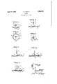
- Fig. 1 is a perspective view of one form which the invention may take.
- Fig. 2 is a top plan view of the embodiment shown in Fig. 1.
- Fig. 3 is a section on the line 3-3 of Fig. 2.
- Fig. 4 is a perspective view of the wire standard used in this embodiment.
- Fig. 5 is a view corresponding to Fig. 3, but showing a slightly difierent embodiment.
- Fig. 6 is a View similarto Figs. 3 and 5, but showing still a diflerent embodiment.
- Fig. 7 is a view similar to Figs. 3, 5, and 6, but showing yet another. embodiment.
- Fig. 8 is a view similar to Fig. 4:, but showing the standard constructed for use in the embodiment of Fig. 7
- the holder comprises a hollow base 1 having a thin top 2 which may conveniently be formed of a sheet metal coated with celluloid or other suitable material upon which may be placed ornamentation.
- the base is shown as being circular in form
- the top is provided with a hole through which extends the standard.
- This standard is preferably made of wire, and, for the sake of convenience, I shall hereinafter refer to it as of wire, although it is to be understood that this expression is not intended to limit the invention.
- the wire has its upper portion bent into the form of a clamp 5, this clamp being shown as formed of two folds 6 between which the card or similar article may be inserted.
- the wire is provided with a vertical shank 7, which extends through the hole in the top 2, and then is bent at an angle to form a radially extending portion 8 which lies closely beneath and in contact with the underside of the top 2.
- the portion 8 is of such length as to extend into the collet 4, and then is bent to form a circular portion 9 adapted to be snapped into position between the collet and the top of the base.
- the wire is resilient and is capable of bending about the bend 10 so as to permit the portion 9 to be snapped into and out of position.
- the base 1 is supplied with the top and the collet, the collet forming a channel extending circumferentially of the base.
- the wire is then bent to the form shown in Fig. 4, and the end 11 of this wire is passed through the hole in the top and then manipulated into the position shown in Figs. 2 and 3, the last step being the snapping of'the portion 9 into the channel formed inside the flange 3.
- Fig. 5 is shown a different embodiment in which the base 1 is made entirely of metal, and the channel for the portion 9 of the wire standard is formed by a flange 3 integral with the top 2*.
- This construction avoids the use ofthe collet and may conveniently be employed where there is no ornamentation to be placed upon the top of the base or where that ornamentation is to be put directly upon the metal of the base.
- celluloid or other coatings are em ployed as in the first described embodiment, it is preferable to use the collet as shown in Figs. 1, 2, and 3.
- the wire used in the embodiment of Fig. 5 is substantially identical with that shown in Fig. 4.
- Fig. 6 is shown another form of the invention in which is provided a base 1 employing a wire of the same form as shown in Fig. 4C.
- the portions 8 and 9 of the wire are held in close contact with the underside of the top by means of a plate 12 provided with a flange 13 fitting within the flange 3 of the top.
- the central portion of the plate 12 is depressed as shown so as to contact with the wire and hold it in place against the underside of the top 2
- FIGs. 7 and 8 there is shown a construction in which is employed a 100 top similar to that shown in Fig. 6, but instead of having the wire of the same form as that shown in Fig. 4:, I use the form shown in Fig. 8.
- this wire forming the standard is the same as that previously described.
- the radially extending portion 14 is shorter than the portion 8, and is shown as bent laterally to form an end portion 15.
- the portions 14 and 15 engage the underside of the top of the base and are held b the plate 12, which is similar in construction and arrangement to the plate described in connection with Fig. 6.
- the portions 14 and 15 cooperate to hold the portion 7 of the standard in its vertical position, but, at the same time, the standard may rotate on the baseas in the other forms.
- the base may be made of any suitable size-and may be provided with ornamentation or advertising matter, as desired.
- Theinvention will find particular utility in K connection with holders for menu cards, al-
- a holder comprising a base formed of sheet material and having a flat top, means forming a channel beneath said top adjacent the periphery thereof, and a wire standard having a vertical shank extending through a hole in said top and having its upper'end provided with a clamp for a card or the like, the lower end of said shank being bent to lie closely beneath the top and in contact'with the underside thereof and extending outwardly to said channel and terminating in a portion lying within said channel.
- a holder comprising a base formed of sheet material and having a flat top, means forming a channel beneath said top adjacent the periphery thereof, and a wire standard having a vertical shank extending through a hole in said top and having its upper end provided with a clamp for a card or the like, the
- said shank being bent to lie closely beneath the top and in contact with the underside thereof and extending outwardly to said channel and terminating in a portion lying within said channel, said portion within the channel being formed of re- 'to the shank to form a portion lying beneath the top and in contact with the underside thereof, said portion being bent again in a 6 plane parallel to the top to form another portion cooperating with said first-named portion to hold said shank in vertical position,
Description
P. O. HOAG April '19, 1932.
HOLDER Filed March 11, 1931 12,12 OR BY ATTORZME ys Patented Apr. 19, 1 932 UNITED sTA'rs PATENT oFFicE IPHILIP O. HOAG, OF MAPLEWOOD, NEW
HOAG- COMPANY, OF
JERSEY, AS SIGNOR TO THE WHITEHEAD & NEWARK, NEW" JERSEY, A CORPORATION OF NEW JERSEY HOLDER Application filed March 11, 1931. Serial No. 521,746.
This invention relates to a novel and improved form of holder, such as may be used to hold menu cards or similar cards. The invention will be best understood from the following description and the annexed drawings, in which I have shown selected embodiments of the invention, and in which:
Fig. 1 is a perspective view of one form which the invention may take.
Fig. 2 is a top plan view of the embodiment shown in Fig. 1.
Fig. 3 is a section on the line 3-3 of Fig. 2.
Fig. 4 is a perspective view of the wire standard used in this embodiment.
Fig. 5 is a view corresponding to Fig. 3, but showing a slightly difierent embodiment.
Fig. 6 is a View similarto Figs. 3 and 5, but showing still a diflerent embodiment.
Fig. 7 is a view similar to Figs. 3, 5, and 6, but showing yet another. embodiment.
Fig. 8 is a view similar to Fig. 4:, but showing the standard constructed for use in the embodiment of Fig. 7
Referring now to Figs. 1, 2, 3, and 4, it
5 will be seen that the holder comprises a hollow base 1 having a thin top 2 which may conveniently be formed of a sheet metal coated with celluloid or other suitable material upon which may be placed ornamentation.
Because of the small scale used, no attempt has been made to show the coating in Fig. 3.
The base is shown as being circular in form,
and its edge is bent downwardly to form a circumferential flange 3 within which is snapped a collet 4.
The top is provided with a hole through which extends the standard. This standard is preferably made of wire, and, for the sake of convenience, I shall hereinafter refer to it as of wire, although it is to be understood that this expression is not intended to limit the invention.
The wire has its upper portion bent into the form of a clamp 5, this clamp being shown as formed of two folds 6 between which the card or similar article may be inserted. The wire is provided with a vertical shank 7, which extends through the hole in the top 2, and then is bent at an angle to form a radially extending portion 8 which lies closely beneath and in contact with the underside of the top 2. In this form, the portion 8 is of such length as to extend into the collet 4, and then is bent to form a circular portion 9 adapted to be snapped into position between the collet and the top of the base. It is to be understood that the wire is resilient and is capable of bending about the bend 10 so as to permit the portion 9 to be snapped into and out of position.
l Vhen the parts are to be assembled, the base 1 is supplied with the top and the collet, the collet forming a channel extending circumferentially of the base. The wire is then bent to the form shown in Fig. 4, and the end 11 of this wire is passed through the hole in the top and then manipulated into the position shown in Figs. 2 and 3, the last step being the snapping of'the portion 9 into the channel formed inside the flange 3.
In Fig. 5 is shown a different embodiment in which the base 1 is made entirely of metal, and the channel for the portion 9 of the wire standard is formed by a flange 3 integral with the top 2*. This construction avoids the use ofthe collet and may conveniently be employed where there is no ornamentation to be placed upon the top of the base or where that ornamentation is to be put directly upon the metal of the base. Where celluloid or other coatings are em ployed as in the first described embodiment, it is preferable to use the collet as shown in Figs. 1, 2, and 3. The wire used in the embodiment of Fig. 5 is substantially identical with that shown in Fig. 4.
In Fig. 6 is shown another form of the invention in which is provided a base 1 employing a wire of the same form as shown in Fig. 4C. In this embodiment, however, the portions 8 and 9 of the wire are held in close contact with the underside of the top by means of a plate 12 provided with a flange 13 fitting within the flange 3 of the top. The central portion of the plate 12 is depressed as shown so as to contact with the wire and hold it in place against the underside of the top 2 Coming now to'Figs. 7 and 8, there is shown a construction in which is employed a 100 top similar to that shown in Fig. 6, but instead of having the wire of the same form as that shown in Fig. 4:, I use the form shown in Fig. 8. The upper portion of this wire forming the standard is the same as that previously described. However, the radially extending portion 14 is shorter than the portion 8, and is shown as bent laterally to form an end portion 15. The portions 14 and 15 engage the underside of the top of the base and are held b the plate 12, which is similar in construction and arrangement to the plate described in connection with Fig. 6. The portions 14 and 15 cooperate to hold the portion 7 of the standard in its vertical position, but, at the same time, the standard may rotate on the baseas in the other forms.
From the above itwill be seen that I have devised a novel and improved form of holder whose'parts may be very cheaply made and assembled. The base may be made of any suitable size-and may be provided with ornamentation or advertising matter, as desired. Theinvention will find particular utility in K connection with holders for menu cards, al-
though, of course, there are other uses which will suggest themselves andv for which the invention is also adapted.
. lVhile I have shown certain selected embodiments of the invention, and certain details of construction, it is to be understood that the invention may be practiced in other forms and may be constructed differently from the detailed forms shown, without departing from the invention.
I claim:
1. A holder-comprising a base having atop of sheet material, a wire having a vertical shank passing through a hole in said top and connected to a'portion engaging said top on its underside, a clamp for a card or the like formed on the-upper end of said shank, and the portion of the wire beneath said top being formed to hold said shank in vertical position while permitting rotation thereof.
2. A holder comprising a base formed of sheet material and having a flat top, means forming a channel beneath said top adjacent the periphery thereof, and a wire standard having a vertical shank extending through a hole in said top and having its upper'end provided with a clamp for a card or the like, the lower end of said shank being bent to lie closely beneath the top and in contact'with the underside thereof and extending outwardly to said channel and terminating in a portion lying within said channel.
3. A holder comprising a base formed of sheet material and having a flat top, means forming a channel beneath said top adjacent the periphery thereof, and a wire standard having a vertical shank extending through a hole in said top and having its upper end provided with a clamp for a card or the like, the
lower end of said shank being bent to lie closely beneath the top and in contact with the underside thereof and extending outwardly to said channel and terminating in a portion lying within said channel, said portion within the channel being formed of re- 'to the shank to form a portion lying beneath the top and in contact with the underside thereof, said portion being bent again in a 6 plane parallel to the top to form another portion cooperating with said first-named portion to hold said shank in vertical position,
and means to hold said portions in contact with said underside of the top.
PHILIP O. HOAG.
Priority Applications (1)
| Application Number | Priority Date | Filing Date | Title |
|---|---|---|---|
| US521746A US1854740A (en) | 1931-03-11 | 1931-03-11 | Holder |
Applications Claiming Priority (1)
| Application Number | Priority Date | Filing Date | Title |
|---|---|---|---|
| US521746A US1854740A (en) | 1931-03-11 | 1931-03-11 | Holder |
Publications (1)
| Publication Number | Publication Date |
|---|---|
| US1854740A true US1854740A (en) | 1932-04-19 |
Family
ID=24077968
Family Applications (1)
| Application Number | Title | Priority Date | Filing Date |
|---|---|---|---|
| US521746A Expired - Lifetime US1854740A (en) | 1931-03-11 | 1931-03-11 | Holder |
Country Status (1)
| Country | Link |
|---|---|
| US (1) | US1854740A (en) |
Cited By (5)
| Publication number | Priority date | Publication date | Assignee | Title |
|---|---|---|---|---|
| US2456302A (en) * | 1944-08-16 | 1948-12-14 | Ladimer M Mocnik | Supporting device |
| US3474555A (en) * | 1967-08-07 | 1969-10-28 | Donald M Mccaffrey | Display card holder |
| US20090260200A1 (en) * | 2008-03-25 | 2009-10-22 | Nikhil Gupta | Stringed bead securement device |
| US20120112024A1 (en) * | 2009-07-01 | 2012-05-10 | Gotzl Werner | Clamp holder for attaching a display means to a base |
| USD1001190S1 (en) * | 2021-09-30 | 2023-10-10 | Wenxiu Deng | Card holder |
-
1931
- 1931-03-11 US US521746A patent/US1854740A/en not_active Expired - Lifetime
Cited By (6)
| Publication number | Priority date | Publication date | Assignee | Title |
|---|---|---|---|---|
| US2456302A (en) * | 1944-08-16 | 1948-12-14 | Ladimer M Mocnik | Supporting device |
| US3474555A (en) * | 1967-08-07 | 1969-10-28 | Donald M Mccaffrey | Display card holder |
| US20090260200A1 (en) * | 2008-03-25 | 2009-10-22 | Nikhil Gupta | Stringed bead securement device |
| US8051541B2 (en) * | 2008-03-25 | 2011-11-08 | Nikhil Gupta | Stringed bead securement device |
| US20120112024A1 (en) * | 2009-07-01 | 2012-05-10 | Gotzl Werner | Clamp holder for attaching a display means to a base |
| USD1001190S1 (en) * | 2021-09-30 | 2023-10-10 | Wenxiu Deng | Card holder |
Similar Documents
| Publication | Publication Date | Title |
|---|---|---|
| US1922900A (en) | Holder for tags, etc. | |
| US1854740A (en) | Holder | |
| US1841690A (en) | Card holder | |
| US1747628A (en) | Safety-pin holder | |
| US2178113A (en) | Holder for towels and other articles | |
| US2316337A (en) | Drapery festoon ring | |
| US1895609A (en) | Flower holder | |
| US2431752A (en) | Spring clamp receptacle for tumblers | |
| US1008352A (en) | Tab for card-index systems. | |
| US1810836A (en) | Bottle rack | |
| US2402374A (en) | Brush rack | |
| US2206522A (en) | Ticket holder | |
| US1993399A (en) | Hat rest | |
| US1634377A (en) | Hanger | |
| US894203A (en) | Folding leaf, flower, or spray stand. | |
| US1483408A (en) | Card holder | |
| US1725932A (en) | Felt-covered base member for electric fans and the like | |
| GB446062A (en) | Improved clip holder for spoons, brushes and the like | |
| US1397818A (en) | Pen or pencil clip | |
| US948576A (en) | Napkin-holder. | |
| US2087032A (en) | Character-carrying device | |
| US1170541A (en) | Memorandum-holder. | |
| US1831307A (en) | Tack fastened stud for snap fasteners | |
| US2207657A (en) | File signal | |
| US696626A (en) | Garment-clasp. |